Protective equipotential bonding for safety fences - Why electrical equalization is essential for occupational safety
Introduction: Electrical safety starts with the safety fence
How can electrical accidents on safety fences be prevented? Time and again, our customers ask us about the necessity of adding equipotential bonding to our protective fence systems. When is it necessary, when is it negligible?
Should a protective fence be integrated into the machine’s protective conductor system? In certain production areas, equipotential bonding is essential when designing and using protective facilities. This is the only way to prevent electric shock to people in the event of a fault by automatically switching off the power supply. However, it is up to the customer to decide whether this is necessary in a specific case – in consultation with their electrician as part of the customer’s risk and hazard assessment. Brühl can provide supportive recommendations and also provide the necessary means for the designs. In the following, we summarize standards and definitions of terms that you will encounter when dealing with this topic in detail.
What is protective equipotential bonding and why is it so important?
What is a potential?
A potential is the voltage (in volts) between a measuring point and a reference point – whereby the earth voltage, i.e. the earth potential, usually forms the reference point for us.
What is equipotential bonding?
Equipotential bonding is a good conductive connection between points with different voltages/potentials – in our case a machine and the protective fence. The different electrical voltage between the bodies is brought to the same potential (level) by the equalization.
See EN 60204-1:2018 3.1 Terms: “3.1.26 Equipotential bonding: Establishing electrical connections between conductive parts to achieve equipotential bonding”
What is equipotential bonding used for?
EN 60204-1:2018 8.1 Equipotential bonding – General information distinguishes between two types of equipotential bonding: protective equipotential bonding and functional equipotential bonding. The former protects persons on a machine against electric shock in the event of a fault.
see EN 60204-1:2018 3.1 Terms: “3.1.49 Protective equipotential bonding: for protection against electric shock”
Functional equipotential bonding, on the other hand, is responsible for reducing the various electrical interference influences and thus ensures smooth operation. As the name suggests, it relates to the function of the machine and therefore has no influence on the protective equipotential bonding function considered in this article. In certain applications, such as dust, recurring movements of parts or the build-up of critical magnetic fields for electronic components, protective equipotential bonding can also serve as functional equipotential bonding.
Protective conductor, earthing and equipotential bonding: how protection works in the event of a fault
How is protective equipotential bonding achieved?
To compensate in the event of a fault, protective conductors are used to divert the current from touchable (machine or fence) parts to earth. This is ensured by the fact that the path of the current through the protective conductor has a lower resistance than a potentially endangered person due to its length, cross-section and material.
The protective conductor system is the entirety of the protective conductor and (in our case) the machine and protective fence. In larger systems, it is necessary to combine several protective conductors in order to keep the resistance of the protective conductor system lower than that of a person at all points.
Protective equipotential bonding conductors are also components of the protective conductor system that interconnect external conductive parts that do not belong to the electrical system.
see EN 60204-1;2018 3.1 Terms: “Protective equipotential bonding can be achieved by protective conductors, protective equipotential bonding conductors and conductive connections between conductive parts of a machine and its electrical equipment.” “3.1.51 Protective conductor: Conductor that diverts a fault current from the body of the electrical equipment to the protective earth (PE) terminal”
“3.1.50 Protective conductor system: Protective conductor and conductive parts that are connected together to protect against electric shock in the event of an insulation fault”
How should safety precautions be optimally implemented in the event of a fault?
If electrically conductive parts of the machine and/or the safety fence unintentionally become live, a fault has occurred. This can be caused, for example, by the damaged insulation of a cable of the machine or of a mobile piece of electrical equipment (e.g. a drill). In this case, the residual current is discharged through the protective conductor system with reduced risk to people and the power supply is interrupted because the circuit breaker (formerly a fuse) trips. Increased protection against accidental contact is provided by a residual current device (RCD, formerly RCD). To ensure the protective function of the RCD switch, the entire system must also be fully integrated into the protective conductor system.
Why protective fences should be part of the protective conductor system – even at a great distance from the machine
Do protective facilities also require protective equipotential bonding?
We refer here to two standards which together state that a) a protective facility made of conductive material around an electrically operated machine is an “external conductive part”, which b) must be integrated into the protective conductor system.
a) In principle, EN ISO 14120: 2016-05 Safety of machinery – Protective facilities must be applied: “5.13 Guards with electrically conductive parts: If guards are made of electrically conductive materials and are used in electrically operated machines, they must be considered as ‘external conductive parts of the machine’ in accordance with EN 60204-1:2018, 8 .” These are defined there in the chapter on terms as follows: “3.1.28 external conductive part: conductive part that does not belong to the electrical system but that can introduce an electrical potential, generally that of a local earth”
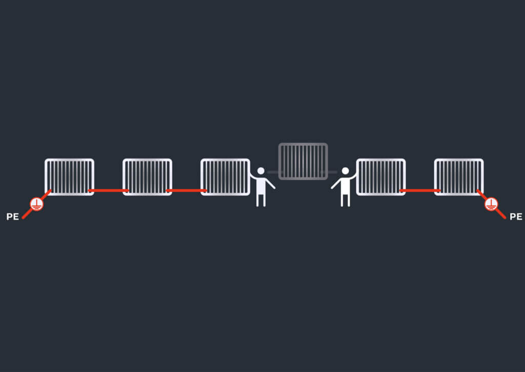
b) According to EN 60204-1:2018, 8 Equipotential bonding, Figure 4 – Example of equipotential bonding for the electrical equipment of a machine, external conductive parts (i.e. also protective fences) must be integrated into the protective conductor system in order to achieve equipotential bonding, provided they are installed at a distance of ≤ 2.5 m from the machine. Within this distance, a person with outstretched arms could touch the machine and the conductive part at the same time. ( Fig. 01)
When is it recommended to connect the protective fence to the protective conductor system despite sufficient distance from the machine?
The attachment of active electrical elements directly to the safety fence (e.g. safety switches) or the use of mobile devices in the vicinity of the safety fence (e.g. drilling machine) can lead to faults that energize the fence due to damage, material fatigue and mechanical stress. If, according to EN 60204-1:2018 Annex A (normative) A1.1, the voltage of these devices exceeds the limit values of 50 V (AC) or 120 V (DC), the protective fence must be integrated into the protective conductor system. For the sake of completeness, it should be noted that these limit values can also be reached by electrostatic charging of the fence (e.g. with resistance or induction welding systems).
Technical implementation: How to integrate fencing systems in line with standards
How is a protective fence integrated into the protective conductor system?
For us, there are two fundamentally different ways of viewing and their associated designs ( Fig. 02):
a) Viewing the protective fence as a structure of parts: Each component of the protective fence is considered as a separate conductive part. The parts are connected to each other with protective conductors and integrated into the protective conductor system.
b) Viewing the protective fence as a unit: In this case, the entire protective fence is viewed as ONE conductive part. This requires in advance that the components of the fence are safely connected to each other . The fence is integrated into the machine’s protective conductor system as usual using protective conductors.
At what intervals must a protective fence be integrated into the protective conductor system?
The frequency with which the protective fence is connected to the machine or earth potential is determined by the level of electrical resistance of the protective conductor system. The resistance results from its length, the cross-section and the material – starting from the point of contact to the protective conductor connection terminal, the earthing. At every point of the fence, it must be ensured that the protective conductor system has a lower resistance than the person touching it. In practice, the resistance is measured and the number of connection points specified by a qualified electrician. A maximum permissible resistance is not specified in the standards. The body resistance of a person is in the range of several hundred ohms, depending on the path through the body. To prevent the current from flowing through the person, the protective conductor system must fall below this value – ideally by a multiple.
Doors, cable ducts and removable fence panels – so the protective conductor circuit remains closed
How is the protective conductor system of the protective fence ensured without interruption?
The removal of a fence section, e.g. for maintenance work, must not lead to an interruption of the protective conductor system – not even for a short time. The function of the equipotential bonding must also be ensured continuously for sections of the protective fence, as the risk of a fault is persistent.
see EN 60204-1:2018 8.2.3 Continuity of the protective conductor system: “If a part is removed for any reason (e.g. routine maintenance), the protective conductor system for the other parts must not be interrupted.”
For example, if the protective fence is only integrated into the protective conductor system on one side, removing a fence section interrupts the connection to the rest of the fence section. Two-sided integration into the machine’s protective potential is recommended. If the customer’s risk assessment indicates that fence panels are to be removed at different points at the same time, a corresponding safety concept must be drawn up.
How are doors integrated into the protective conductor system?
Doors are part of the protective fence and their opening must not lead to an interruption of the protective conductor system. Therefore, the integration of the door (including the door wing) must be ensured on both sides.
Do conductive cable ducts mounted on the protective fence have to be integrated into the protective conductor system?
Yes, because conductors with high voltages can also run there.
In industrial environments, not only conductors with protective (SELV) and functional extra-low voltages (PELV, FELV) are installed in cable ducts, but also those with high electrical power and voltages. For safety reasons, it is therefore advisable to integrate cable trunking into the protective conductor system using protective conductors or protective equipotential bonding conductors.
Can or must the functionality of the protective conductor system be tested?
According to both EU Directive 2009/104/EC (operator regulation) and to comply with MRL 2006/42/EC (manufacturer regulation), testing of the protective conductor system must be carried out by a qualified electrician prior to initial commissioning in accordance with the state of the art by measuring the resistance. During operation, the operator is responsible for having the testing carried out at regular intervals, as well as after modifications or repairs. In Germany, this has been laid down at national level in the Ordinance on Industrial Safety and Health:
see Industrial Safety Regulation (BetrSichV) §6 (3) 1: “The employer must ensure that (…) 3. all forms of energy and materials used and generated can be safely supplied and discharged.”
What are the requirements for protective conductors, connection points and labeling?
How must a protective conductor be constructed?
EN 60204-1:2018 provides recommendations on the material, cross-section and design of protective conductors and protective equipotential bonding conductors: A protective conductor made of copper must have a cross-section of at least 2.5 mm² or 4 mm² if the mechanical protection is insufficient. Detailed instructions are provided for the calculation or selection of the cross-section. The standard also provides information on exceptions for connected parts that may be used as protective conductors. see EN 60204-1:2018, 8.2.2 Protective conductors: “Copper conductors are preferable. If a conductor material other than copper is used, its electrical resistance per unit length must not exceed that of the permissible copper conductor. The cross-section of such conductors must not be less than 16 mm² for reasons of mechanical durability. (…) Each protective conductor must: be part of a multicore cable; or be in a housing together with the outer conductors; or have a cross-section of at least 2.5 mm² Cu or 16 mm² Al if protection against mechanical damage is provided; 4 mm² Cu or 16 mm² Al if protection against mechanical damage is not provided. (…)”
What characterizes a protective equipotential bonding conductor?
Permanently conductive connection, mechanically and thermally resilient, identifiable by color, symbol or letters.
Protective equipotential bonding conductors establish a permanent conductive connection between external conductive parts. There is no clear definition of this in the standards. As they act as part of the protective earth conductor system, the following condition applies: see EN 60204-1:2018, 8.2 Protective earth conductor system: “8.2.1 General: All parts of the protective earth conductor system must be designed to withstand the highest thermal and mechanical stresses due to earth fault currents that could flow in the respective part of the protective earth conductor system.”
What requirements must protective conductor connection points meet?
Can only be used for this purpose, mechanically secured, clearly marked and designed in accordance with standards.
The protective conductor connection point is usually a mechanical joining element, e.g. a screw connection, which is located on the conductive part (e.g. fence post, machine, main earthing terminal …) and is subject to special requirements. These are set out in detail in EN 60204-1:2018. Protective conductor connection points must not be used for any other function. see EN 60204-1 8.2.4 Protective conductor connection points: “All protective conductors must be connected in accordance with 13.1.1. Protective conductor connection points must not be used for the attachment of e.g. devices or parts.” see EN 60204-1 8.2.4, 13.1.1: “All connections, in particular of the protective conductor system, must be secured against self-loosening. The connection means must be suitable for the cross-section and type of conductor to be connected. The connection of two or more conductors to one terminal is only permitted if the terminals are designed for this purpose. However, only one protective conductor may be connected per terminal connection point. (…)”
How can protective conductors, protective conductor connection points and protective equipotential bonding conductors be identified?
Color coding (green-yellow), graphic symbol (IEC 60417-5019) or letter combination (PE or PB).
According to EN 60204-1, these conductive, safety-relevant components must be identified either by color, by a graphic symbol or by a combination of letters. see EN 60204-1 8.2.2 Protective conductor: “Protective conductors must be identifiable in accordance with 13.2.2.” see EN 60204-1 13.2.2 Identification of the protective conductor/protective bonding conductor: “The protective conductor/protective bonding conductor must be clearly distinguishable from other conductors by shape, arrangement, marking or color. If identification is by color only, the two-color combination must be GREEN-YELLOW be used over the entire length of the conductor. (…) However, these conductors must be clearly marked at the ends or in accessible locations by the graphic symbol according to IEC 60417-5019:2006-08 ( Fig. 04 a) or with the letters PE or by the two-color combination GREEN-YELLOW be identifiable. Exception: Protective bonding conductors can be identified with the letters PB and/or with the symbol according to IEC 60417-5021:2002-10 ( Fig. 04 b) must be marked.”
Doesn’t the powder-coating of a protective fence already protect against the risk of electric shock?
The powder-coating serves as corrosion protection and not as an insulating layer. Full insulation cannot be guaranteed with powder-coating, as 100% coverage of the coating, e.g. at the wire transition, cannot be guaranteed.
Conclusion: Safety starts with earthing – correctly integrating protective fences into the protective conductor system
For Brühl, safety is paramount. We therefore recommend integrating the protective fence systems into the protective conductor system of your plant. We can provide you with safe and legally compliant overall solutions. Both the use of protective conductors and the integration of protective equipotential bonding conductors into the fencing system is possible, see Fig. 05-09. The applicable legal regulations with EN ISO 14120:2013, EN 60204-1:2018 and the Work Equipment Usage Ordinance 2009/104/EC (BetrSichV in Germany) are binding throughout the EU.